Zener Diode
Aim
To study the I-V Characteristics of a Zener Diode.
Apparatus
- Zener Diode
- Battery
- Connecting Wires
- Resistances
- Voltmeter
- Ammeter
Theory
Forward Biasing
An external voltage is applied with the polarity such that the negative terminal of the battery is connected to the n-side of the junction and the positive terminal of the battery is connected to the p-side. This configuration is called forward bias.
Reverse Biasing
The negative terminal of the battery is connected to the p-side of the junction, and the positive terminal is connected to the n-side. This configuration is called reverse bias. Zener diodes are specifically used in reverse bias mode.
Circuit Diagram
Forward Bias:

Reverse Bias:
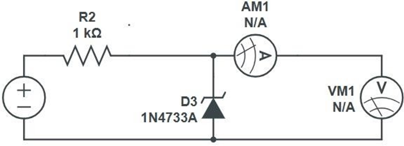
Procedure
- Connect a current-limiting resistor in series with the Zener diode.
- Vary the value of the input DC supply in steps.
- Note down the ammeter and voltmeter readings for each step.
- Use the collected data to plot the I-V graph.
Observations
Forward Bias:
| S.No. | Voltage (V) | Current (mA) |
|---|---|---|
| 1 | ||
| 2 | ||
| 3 | ||
| 4 | ||
| 5 | ||
| 6 |
Reverse Bias:
| S.No. | Voltage (V) | Current (mA) |
|---|---|---|
| 1 | ||
| 2 | ||
| 3 | ||
| 4 | ||
| 5 | ||
| 6 | ||
| 7 | ||
| 8 | ||
| 9 |
Precautions
- Keep the circuit neat and clean.
- Ensure that the power supply and ammeter are working properly.
Result
The V-I Characteristic Graphs/Curves of the Zener Diode (both in reverse and forward biases) are obtained and verified with their proven results.
- Breakdown Voltage:
- Maximum Forward Current: 1A