Experiment 5: Thevenin’s Theorem
Aim
Verification of Thevenin’s Theorem
Components and Equipment Required
- Multimeter
- Power supply
- Breadboard
- 3 Resistors
- Connecting wires
Theory
Thevenin’s theorem states that a linear two-terminal circuit can be replaced by an equivalent circuit consisting of a voltage source $V_{Th}$ in series with a resistor $R_{Th}$, where $V_{Th}$ is the open-circuit voltage at the terminals and $R_{Th}$ is the input or equivalent resistance at the terminals when the independent sources are turned off.
The basic steps for solving a circuit using Thevenin’s Theorem are as follows:
1. Remove the load resistor $R_L$ or component concerned.
2. Find $R_{Th}$ by shorting all voltage sources or by open-circuiting all the current sources.
3. Find $V_{Th}$ by the usual circuit analysis methods.
4. Find the current flowing through the load resistor $R_L$.
Formulas used:
$$I_L = \frac{V_{TH}}{R_{TH} + R_L}$$
Circuit Diagram
Figure 1: Original Circuit
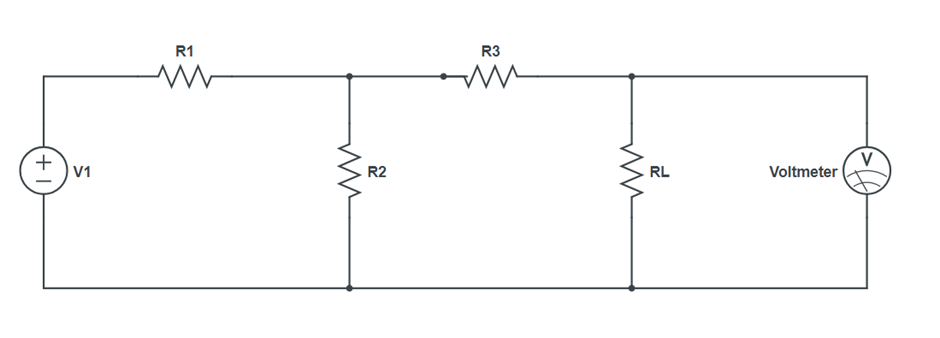
Figure 2: For $V_{Th}$
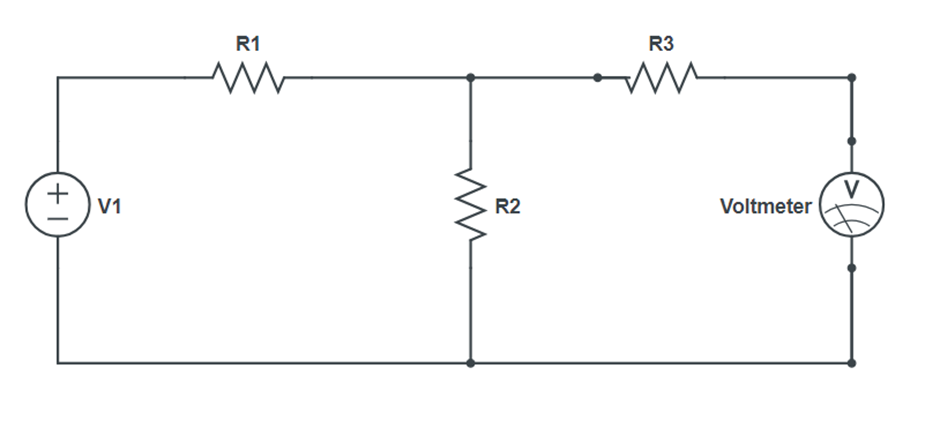
Figure 3: For $R_{Th}$

Procedure
- Connect the circuit as shown in Figure 1.
- Set the particular voltage value and note down all readings.
- Connect the circuit as in Figure 2 to obtain the Thevenin voltage. Remove the load resistor from the original circuit and calculate the voltage across the open terminals to find $V_{Th}$.
- Connect the circuit as in Figure 3 to obtain Thevenin resistance. Remove all power sources (short voltage sources and open current sources) and calculate total resistance between open terminals to find $R_{Th}$.
Observation Table
| $R_L (Ω)$ | $V_L (V)$ (Original Circuit) | $I_L (mA)$ (Original Circuit) | $V_L (V)$ (Thevenin Circuit) | $I_L (mA)$ (Thevenin Circuit) |
|---|---|---|---|---|
Result
Thus, the Thevenin’s Theorem is verified.
Precautions
- Keep the circuit neat and clean.
- Ensure the power supply and ammeter are working properly.
- Avoid short circuiting the output terminals.