Experiment 7: Norton’s Theorem
Aim:
Verification of Norton’s Theorem
Components and Equipment Required:
- Variable power supply
- 3 resistors
- Resistance box
- Constant current source
- Connecting wires
Theory:
Norton’s theorem states that a linear two-terminal circuit can be replaced by an equivalent circuit consisting of a current source $I_N$ in parallel with a resistor $R_N$, where $I_N$ is the short-circuit current through the terminals and $R_N$ is the input or equivalent resistance at the terminals when the independent sources are turned off.
The Norton’s equivalent current $I_N$ is the short-circuit current between the terminals when all voltage sources in the network are short-circuited and all current sources are open-circuited.
$$I = \frac{V_s}{R_1 + \frac{R_2 \cdot R_3}{R_2 + R_3}}$$ $$R_{int} = R_2 + \frac{R_1 \cdot R_3}{R_1 + R_3}$$
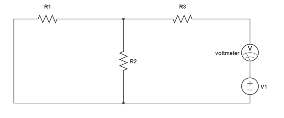
Circuit Diagram:
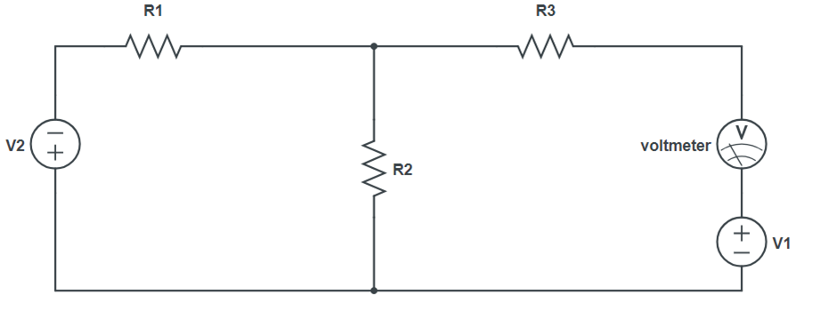
Procedure:
- Make the circuit on a breadboard with a resistance box as $R_L$ and a multimeter to measure voltage $V_L$ across $RL$. Set the output of the power supply.
- Take out resistance from the resistance box and note down $V_L$ as measured by the multimeter.
- Vary $R_L$ and note down the corresponding value of $V_L$.
- Note down the load current:
$$ I_L = \frac{V_L}{R_L} $$
for each value of $R_L$.
- Remove $R_L$, connect an ammeter between terminals A and B, and measure the short-circuit current $I_{SC}$. This is the Norton equivalent current $I_N$.
- Remove $R_L$ from the circuit and replace the power supply with a short circuit. Measure the resistance between A and B directly with a multimeter.
- Make the Norton’s equivalent circuit, adjust the current from the current source, take out the resistance, and measure the lower resistance with the multimeter connected in series with $R_L$.
- Vary $R_L$ and note down the corresponding values of $I_1$.
- Compare the values of load current in the original circuit and in the Norton’s equivalent circuit for each value of $R_L$.
- Note: When a current source is not available, connect a power supply in series with a variable resistance and a milliammeter in place of the current source.
Observation Table:
| R (Ω) | $V_L$ (V) | $I_L$ (mA) | $V_N$ (V) | $I_N$ (mA) |
|---|---|---|---|---|
Result:
The measured values of the load current and load voltage in the original circuit match the corresponding values in the Norton’s equivalent circuit.
Precautions:
- The current in the circuit should remain constant for all observations.
- Set the voltmeter point at 0.
- Check connections properly.