Experiment 6: MPT Theorem
Aim
To verify the Maximum Power Transfer Theorem.
Components and Equipment Required
- Breadboard
- Multimeter
- Connecting wires
- DC power supply
- Resistor
- Resistance box
Theory
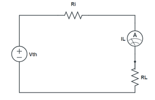
According to the Maximum Power Transfer Theorem, a linear two-terminal network consisting of a voltage source and resistance will transfer maximum power to a load connected across its terminals when the load resistance $R_L$ is equal to the Thevenin’s resistance R_th of the network:
$R_L = R_{th}$
The power delivered to the load is maximum under this condition.
Formula Used
$P_{\text{max}} = \left( \frac{V_{\text{th}}}{R_1 + R_L} \right)^2 \cdot R_L $
Circuit Diagram
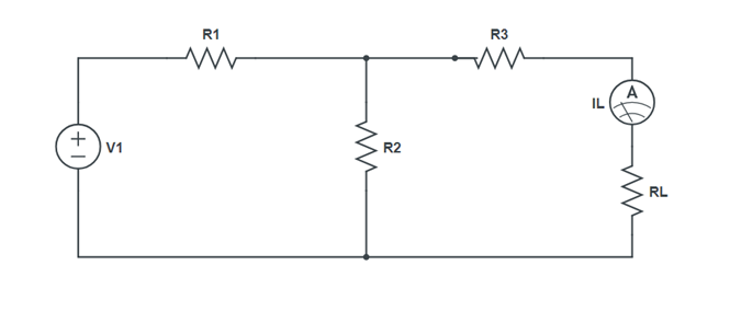
Procedure
- Make the circuit on a breadboard with a resistance box as $R_L$.
- Connect a digital multimeter across $R_L$ to measure the load voltage $V_L$.
- Vary $R_L$ using the resistance box and note the corresponding $V_L$
- Calculate the power $P_L$ for each value of $R_L$.
- Plot $P_L$ as a function of $R_L$.
Observation Table
| $R_L$ (Ω) | $V_L$ (V) | $P_L$ (W) | $P_L$ (mW) |
|---|---|---|---|
Result
The output power $P_L$ is maximum for $R_L = R_{th}$. Hence, the Maximum Power Transfer Theorem is verified.
Precautions
- The output voltage of the power supply should remain constant during the experiment.
- The internal resistance of the power supply, if any, is neglected.
- The power supply should be switched off while making or breaking the circuit.