Unijunction Transistor(UJT)
Aim
To study the I-V characteristics of the Unijunction Transistor (UJT).
Apparatus
- Unijunction Transistor (UJT)
- 2 Batteries
- Ground Element
- Connecting Wires
- Resistors
- Voltmeter
- Ammeter
Theory
A Unijunction Transistor (UJT) is a semiconductor device with a single junction. It has three terminals:
1. Emitter (E)
2. Base 1 (B₁)
3. Base 2 (B₂)
The base is formed by a lightly doped n-type silicon bar with two ohmic contacts, B₁ and B₂, at its ends. The emitter, which is of p-type material, is heavily doped. The resistance between B₁ and B₂ when the emitter is open-circuited is known as the inter-base resistance.
The UJT is essentially a bar of n-type semiconductor material into which p-type material has been diffused at a specific point along its length.
Circuit Diagram
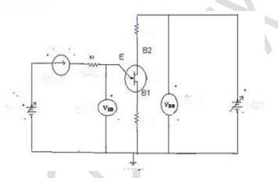
Procedure
- Connect the circuit as per the provided diagram.
- Fix the output voltage (Vᵦ₁ᵦ₂) at a constant level.
- Vary the input voltage (Vₑ) and note the corresponding emitter current (Iₑ).
- Repeat this procedure for different values of output voltage (Vᵦ₁ᵦ₂).
- Plot a graph between emitter voltage (Vₑ) and emitter current (Iₑ) for each value of Vᵦ₁ᵦ₂.
Observations
| S. No. | Vᵦ₁ᵦ₂ (volts) | Vₑ (volts) | Iₑ (mA) |
|---|---|---|---|
| 1 | |||
| 2 | |||
| 3 | |||
| 4 | |||
| 5 | |||
| 6 |
Precautions
- Do not exceed the rated voltage or current of the UJT to avoid damage.
- Ensure that the voltmeter and ammeter are connected with the correct polarities.
- Double-check all connections against the circuit diagram before switching on the power supply.
- Keep the circuit neat and organized to avoid any short circuits or connection errors.
Result
The I-V characteristic graphs of the Unijunction Transistor (UJT) are successfully obtained and verified with proven results.